-->
Now... the how-to part...
The concept behid it was to use two locators, the first locator is going to be the one that attached to the object. The other one is going to act as the distance controler... well sort of.
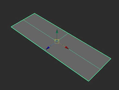
Let's try create a polyPlane. Scale it or tweak it any way you like, as long as it's easy to see the later result. In my example, my setting for the polyPlane is:
- scaleX : 3
- subdivision width : 2
- subdivision height : 2

-->
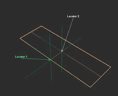
Next... create two locators. Translate the first locator 0.5 units in Z axis. That should move the locator right on to the edge of the polyPlane, that is if you follow my settings. If not, then just try to move the locator as close possible right on the edge of the polyPlane. Leave the position unchanged for the second Locator. See below pic.

-->
For the second locator, I prefer to point constrain with maintain offset set to off. So that the second locator will have the exact position value of the polyPlane. It can actually parented to the polyPlane, but for some cases where using point constraint will have exact position value. For example, if after we create polyPlane then we freeze transformation. That'll make the translate value of the polyPlane zero. Now that would create problem when we hook that info into distanceBetween node.
Open hypershade. Create distanceBetween node. Select two locators, then in hypershade menu – Graph – Add Selected to Graph. That should put in those locator nodes into the hypershade. If there any unwanted nodes appeared in the hypershade, then select those unwanted nodes, go to Graph – Remove Selected Nodes. That'll get rid of them.
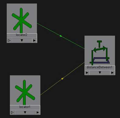
After we create distanceBetween node, connect output of the translate attribute from both locators into the input of the distanceBetween node. To do this, middle click & drag the first locator into distanceBetween node, and choose Other. This will open up connection editor automatically. In the outputs of the first locator, find attribute named translate. Click it. Then in the inputs of the distanceBetween node, find attribute named point1. Click it. Both attributes from those two objects will turn to italics, meaning both attributes are now connected.
Ok, now let's connect the second locator into the input of the distanceBetween node. We could do it with the above method, or connect it by command line.
Type in :
connectAttr -f locator2.translate distanceBetween1.point2
Meaning...?
connectAttr will tell maya to connect attribute between two objects obviously. So, that line basically tell maya to connect attributes (connectAttr) by force (-f) from locator2.translate into distanceBetween.point2. Why distanceBetween.point2..? because the point attribute already has connection with first locator.
Now we've connect the second locator to distanceBetween node using command line, or in other word by mel (Maya Embedded Language). Scary huh..?

-->
As you can see the pic above... that's the result after we connect two locators into distanceBetween node.
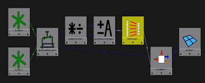
Create four other nodes, multiplyDivide – plusMinAverage – setRange and condition nodes.
Follow these steps carefully...
For condition node:
- Connect distanceBetween1.distance to input of condition.firstTerm. You may do this either by connection editor or by mel. It's your call.
- Change the operation of condition node to “less than”
- Set the condition node secondTerm value to the same value as firstTerm.
- Set the condition node colorIfFalse to zero in x field (the first field).
For multiplyDivide node:
- connect distanceBetween.distance to input of multiplyDivide node input1X.
- Change the operation of multiplyDivide to “divide”.
- Set input2X value with the same value as input1X.
- Set both value of input1Y and input2Y to 1.
For setRange node:
- Set oldMax first field value to 1.
- Set Max first field value to 2.. or whatever but should be greater than zero. This is the amount of how many units the object is going to be translated. You'll see...
Now... lets connect all of them.
- Connect the multiplyDivide output1Y to input of plusMinusAverage inputD[0]. We already knew that both value in multiplyDivide input1Y and input2Y is 1. With the operation sets to “divide”, then 1 divide by 1 will result 1. Actually we need to have value 1 in the first input1D[0].
- Connect the multiplyDivide output1X to input of plusMinAverage input1D[1]. In normal condition, that is if we haven't move first locator, both value in input1X and input2X of multiplyDivide node will be the same, except that input1X is dynamicaly keeps updating whenever the first locator is being moved. Why we hook this value into the second input of the plusMinAverage input1d[1]..? Coz we want that polyPlane will move gradually in Y axis (in this example) when the first locator are moving closer (in specified range) to the polyPlane. Keep going for now.
- Connect output from plusMinAverage output1D to input of setRange valueX.
- Connect output from setRange outValueX to input of condition colorIfTrueR.
- Connect output of condition outColorR to input of polyPlane translateY.

-->
Try to move the first locator towards or away from the polyPlane. If everything was set up correctly, when the first locator is moving closer toward the polyPlane, the polyPlane will move gradually in Y axis direction. But when the first locator is moving away from polyPlane, then the polyPlane will move gradually to its default position.
Now for some explanation...
The distanceBetween node will keeps “recording” the distance value between both two locators. That distance value is passed on, first into the multiplyDivide node input1X. Secondly, the distance value is passed on into firstTerm of condition node.
While in multiplyDivide node, we set operation to divide and set both value of input1Y and input2Y to 1. So when input1Y divide by input2Y will give result of 1. We'll need this value later when we pass this value to plusMinAverage. Without using plusMinAverage, the polyPlane will pop its translation. It's kind of having value from 1 goes to zero (when locator is moving closer to polyPlane) but then goes to 1 again after the locator is moving away.
So we need to reverse that value. We want that when the locator is away on specific distance (in this case it's set to 0.5 in secondTerm of condition node), the polyPlane will be stay still in its default position which is 0 0 0 in translation order.But when the locator is getting closer to the center of polyPlane, then the polyPlane will move in Y axis gradually, from zero to 2 units max (The value from setRange Max). We got this by subtracting 1 (The division result of input2Y & input2Y of multiplyDivide node) by division result of input1X & input2X multiplyDivide node.
The setRange node acts more like a normalizer for the value passed on by the plusMinusAverage node. Without setRange node, it's hard to control the amount of the translation we want for the polyPlane. But with setRange node, we could control the amount in the max value.
Now once everything has been hooked up, it's all up to condition node to decide when the polyPlane will move or not. In condition node, with operation set to “less than”, so when the firstTerm value is less than the secondTerm value, then condition node will use whatever value in colorIfTrue. This value is dynamicaly changing according to the setRange and all behind that's I've been telling you just now.
Well that's just a basic concept that I can think of at the moment to create such animation. I know it's very straight forward just to animate the polyPlane by keyframe. But that is if only one polyPlane that is going to by tranlated. What if we have lots of bunch of polyPlanes, let's say 50 or even 100 polyplanes?? Are we going to animate them by keyframe? No, of cource not. By using mel to auto setup for this type of rig into all of available polyPlanes, it's just a matter moving one single locator to get them all moving.
Komentar
Posting Komentar
Monggo komennya